

SN74AUP1G79DSFR
Product Overview
- Category: Integrated Circuit (IC)
- Use: Logic Gate
- Characteristics: Single Positive-Edge-Triggered D-Type Flip-Flop
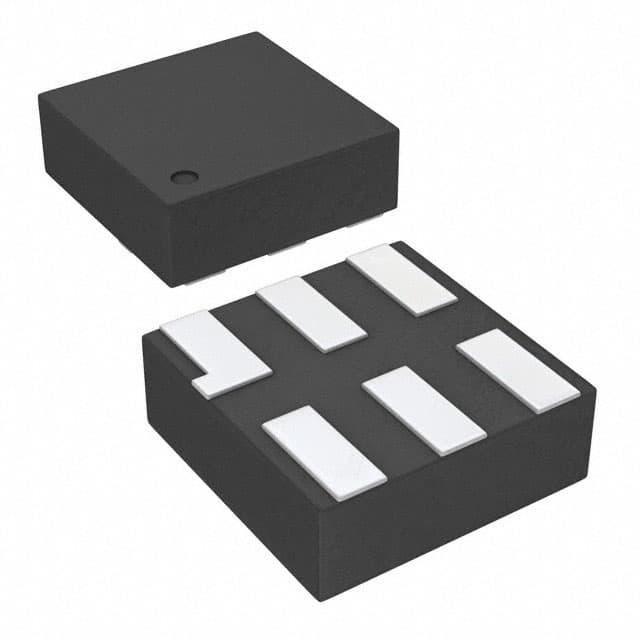
- Package: 6-DSBGA (0.8x0.8 mm)
- Essence: This IC is a single positive-edge-triggered D-type flip-flop designed for use in various digital applications.
- Packaging/Quantity: Available in tape and reel packaging with 3000 units per reel.
Specifications
- Supply Voltage Range: 0.8V to 3.6V
- Input Voltage Range: -0.5V to VCC + 0.5V
- Operating Temperature Range: -40°C to 85°C
- Propagation Delay: 2.4 ns (typical)
- Output Drive Capability: ±24 mA at 3.3V
- Latch-Up Performance: ±100 mA per JESD 78, Class I
Detailed Pin Configuration
The SN74AUP1G79DSFR has the following pin configuration:
____
   Q |1    6| VCC
   D |2    5| GND
 CLK |3    4| ~CLR
       ----
Functional Features
- Single positive-edge-triggered D-type flip-flop with asynchronous clear functionality.
- High-speed operation with low power consumption.
- Wide supply voltage range allows compatibility with various systems.
- Schmitt-trigger inputs provide hysteresis for improved noise immunity.
- Small package size enables space-saving designs.
Advantages and Disadvantages
Advantages: - High-speed operation ensures efficient data processing. - Low power consumption helps conserve energy. - Wide supply voltage range allows for compatibility with different systems. - Schmitt-trigger inputs enhance noise immunity, ensuring reliable operation. - Small package size enables compact and space-saving designs.
Disadvantages: - Limited number of flip-flops in a single IC may restrict the complexity of circuits that can be implemented. - Lack of additional features or functionalities compared to more advanced flip-flop designs.
Working Principles
The SN74AUP1G79DSFR operates as a positive-edge-triggered D-type flip-flop. It stores and outputs data based on the rising edge of the clock signal (CLK). The asynchronous clear input (~CLR) resets the flip-flop to a known state when activated. The flip-flop is designed to operate within a specified supply voltage range and temperature range, ensuring reliable performance.
Detailed Application Field Plans
The SN74AUP1G79DSFR can be used in various digital applications, including but not limited to:
- Microcontrollers and microprocessors
- Communication systems
- Data storage devices
- Industrial automation
- Consumer electronics
- Automotive electronics
Its small package size and low power consumption make it suitable for portable devices, while its high-speed operation and noise immunity make it ideal for applications requiring reliable data processing.
Detailed and Complete Alternative Models
- SN74AUP1G79DCKR
- SN74AUP1G79DBVR
- SN74AUP1G79DRLR
- SN74AUP1G79DCTR
- SN74AUP1G79DRLRG4
These alternative models offer similar functionality and characteristics to the SN74AUP1G79DSFR, providing flexibility in choosing the most suitable option for specific design requirements.
Word count: 404 words
10個與SN74AUP1G79DSFR在技術方案中應用相關的常見問題與解答
Sure! Here are 10 common questions and answers related to the application of SN74AUP1G79DSFR in technical solutions:
Q1: What is the SN74AUP1G79DSFR? A1: The SN74AUP1G79DSFR is a single positive-edge-triggered D-type flip-flop with clear, designed for 1.8-V to 3.6-V VCC operation.
Q2: What is the purpose of the SN74AUP1G79DSFR? A2: The SN74AUP1G79DSFR is used to store and transfer data in digital circuits. It can be used in various applications such as memory units, counters, and registers.
Q3: What is the operating voltage range of the SN74AUP1G79DSFR? A3: The SN74AUP1G79DSFR operates within a voltage range of 1.8V to 3.6V.
Q4: How many inputs does the SN74AUP1G79DSFR have? A4: The SN74AUP1G79DSFR has one data input (D), one clock input (CLK), and one clear input (CLR).
Q5: What is the maximum clock frequency supported by the SN74AUP1G79DSFR? A5: The SN74AUP1G79DSFR can support clock frequencies up to a maximum of 100 MHz.
Q6: Can the SN74AUP1G79DSFR be used in battery-powered devices? A6: Yes, the SN74AUP1G79DSFR can be used in battery-powered devices as it operates within a low voltage range of 1.8V to 3.6V.
Q7: Does the SN74AUP1G79DSFR have any power-saving features? A7: Yes, the SN74AUP1G79DSFR has a low-power consumption design, making it suitable for applications where power efficiency is important.
Q8: Can the SN74AUP1G79DSFR be cascaded with other flip-flops? A8: Yes, multiple SN74AUP1G79DSFR flip-flops can be cascaded together to create larger storage units or more complex circuits.
Q9: What is the package type of the SN74AUP1G79DSFR? A9: The SN74AUP1G79DSFR is available in a small SOT-23 package, which is commonly used in compact electronic devices.
Q10: Are there any application notes or reference designs available for the SN74AUP1G79DSFR? A10: Yes, Texas Instruments provides application notes and reference designs for the SN74AUP1G79DSFR, which can help users understand its usage in different technical solutions.
Please note that these answers are general and may vary depending on specific requirements and use cases. It's always recommended to refer to the datasheet and documentation provided by the manufacturer for accurate information.