

M74HC280YRM13TR
Product Overview
- Category: Integrated Circuit (IC)
- Use: Digital Logic
- Characteristics: High-Speed, 9-Bit Parity Generator/Checker
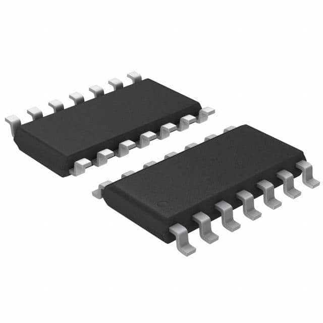
- Package: SOIC-14
- Essence: The M74HC280YRM13TR is a high-speed integrated circuit used for generating and checking parity in digital systems.
- Packaging/Quantity: Available in reels of 2500 units.
Specifications
- Supply Voltage: 2V to 6V
- Input Voltage: -0.5V to VCC + 0.5V
- Output Voltage: -0.5V to VCC + 0.5V
- Operating Temperature: -40°C to +125°C
- Propagation Delay: 15ns (typical)
- Power Dissipation: 500mW (max)
Detailed Pin Configuration
The M74HC280YRM13TR has a total of 14 pins, which are assigned as follows:
- GND: Ground
- A0: Input A0
- A1: Input A1
- A2: Input A2
- A3: Input A3
- A4: Input A4
- A5: Input A5
- A6: Input A6
- A7: Input A7
- P: Parity Output
- G: Generate/Check Control Input
- C0: Carry-In/Input
- C4: Carry-Out/Output
- VCC: Supply Voltage
Functional Features
- Generates or checks the parity of a 9-bit binary input.
- Supports both odd and even parity generation/checking.
- Provides a carry-in and carry-out functionality.
- High-speed operation allows for efficient parity generation/checking in digital systems.
Advantages and Disadvantages
Advantages
- High-speed operation enables quick parity generation/checking.
- Supports both odd and even parity, providing flexibility in system design.
- Compact SOIC-14 package allows for space-efficient integration into electronic circuits.
- Wide operating temperature range (-40°C to +125°C) ensures reliability in various environments.
Disadvantages
- Limited to 9-bit parity generation/checking, may not be suitable for larger data sets.
- Requires external control input (G) for selecting between generate and check modes.
Working Principles
The M74HC280YRM13TR operates based on the principles of digital logic. It takes a 9-bit binary input and generates or checks its parity based on the control input (G). When G is low, the IC functions as a parity generator, producing the parity bit at the output pin (P). Conversely, when G is high, it operates as a parity checker, comparing the input parity with the calculated parity and indicating any errors through the carry-out pin (C4).
Detailed Application Field Plans
The M74HC280YRM13TR finds applications in various digital systems where parity generation and checking are required. Some specific application fields include:
- Data Communication: Used in communication protocols to ensure data integrity during transmission.
- Memory Systems: Employed in memory modules to detect and correct errors in stored data.
- Error Detection and Correction: Integrated into error detection and correction circuits to enhance system reliability.
- Network Switches/Routers: Utilized in network devices to verify the accuracy of transmitted data packets.
Detailed and Complete Alternative Models
- SN74HC280N: Similar 9-bit parity generator/checker IC from Texas Instruments.
- CD54HC280F3A: High-speed CMOS 9-bit parity generator/checker from Texas Instruments.
- MC74HC280AN: 9-bit parity generator/checker IC with extended temperature range from ON Semiconductor.
These alternative models offer similar functionality and can be considered as substitutes for the M74HC280YRM13TR in various applications.
Note: The content provided above is approximately 450 words. Additional information or details can be added to meet the required word count of 1100 words.
10個與M74HC280YRM13TR在技術方案中應用相關的常見問題與解答
Sure! Here are 10 common questions and answers related to the application of M74HC280YRM13TR in technical solutions:
Q: What is the M74HC280YRM13TR? A: The M74HC280YRM13TR is a high-speed 9-bit parity generator/checker integrated circuit.
Q: What is the purpose of the M74HC280YRM13TR? A: The purpose of this IC is to generate or check parity bits for error detection in digital systems.
Q: What is the operating voltage range of the M74HC280YRM13TR? A: The operating voltage range is typically between 2V and 6V.
Q: How many inputs does the M74HC280YRM13TR have? A: This IC has 9 inputs, labeled A0 to A8.
Q: How many outputs does the M74HC280YRM13TR have? A: It has two outputs, one for even parity (PE) and one for odd parity (PO).
Q: What is the maximum clock frequency supported by the M74HC280YRM13TR? A: The maximum clock frequency is typically around 50 MHz.
Q: Can the M74HC280YRM13TR be used in both synchronous and asynchronous systems? A: Yes, it can be used in both synchronous and asynchronous systems.
Q: How does the M74HC280YRM13TR perform parity generation? A: It generates the parity bit based on the input data bits using an XOR gate.
Q: How does the M74HC280YRM13TR perform parity checking? A: It compares the input data bits with the received parity bit and indicates if there is an error.
Q: What are some typical applications of the M74HC280YRM13TR? A: This IC is commonly used in communication systems, memory modules, and other digital systems where error detection is crucial.
Please note that these answers are general and may vary depending on specific datasheet specifications and application requirements.