

Encyclopedia Entry: 74ACT574SJ
Product Overview
Category
The 74ACT574SJ belongs to the category of integrated circuits (ICs) and specifically falls under the family of flip-flops.
Use
This IC is commonly used in digital electronic systems for storing and transferring data. It serves as an octal D-type flip-flop with a transparent latch.
Characteristics
- High-speed operation: The 74ACT574SJ is designed to operate at high clock frequencies, making it suitable for applications requiring fast data transfer.
- Low power consumption: This IC is optimized for low power consumption, making it energy-efficient.
- Wide operating voltage range: It can operate within a wide voltage range, typically between 2V and 6V.
- Compatibility: The 74ACT574SJ is compatible with both TTL and CMOS logic families, allowing for easy integration into various digital systems.
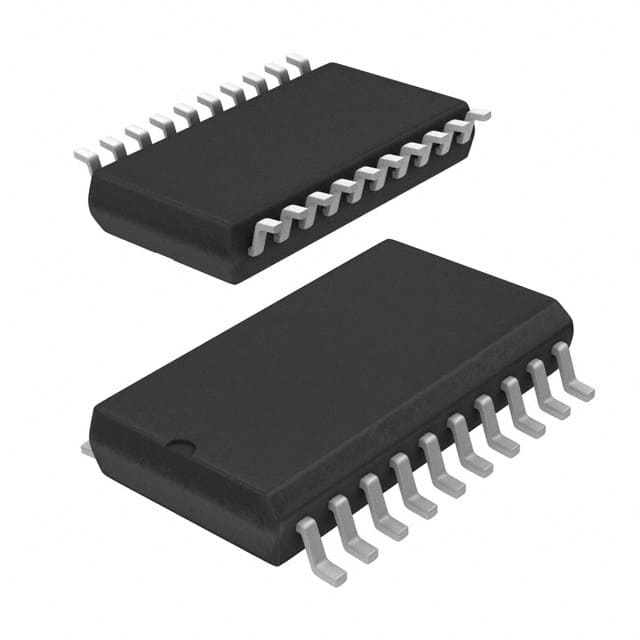
Package
The 74ACT574SJ is available in a small outline integrated circuit (SOIC) package. This package offers compactness and ease of handling during assembly.
Essence
The essence of the 74ACT574SJ lies in its ability to store and transfer data efficiently within digital systems. It provides a reliable and versatile solution for data storage and synchronization.
Packaging/Quantity
The 74ACT574SJ is typically sold in reels or tubes, containing multiple units per package. The exact quantity may vary depending on the supplier.
Specifications
- Supply Voltage Range: 2V to 6V
- Operating Temperature Range: -40°C to +85°C
- Input/Output Logic Compatibility: TTL and CMOS
- Number of Flip-Flops: 8 (octal)
- Clock Frequency: Up to XX MHz (specific value depends on the variant)
Detailed Pin Configuration
The 74ACT574SJ has a total of 20 pins, each serving a specific function. The pin configuration is as follows:
- Pin 1: Data Input (D0)
- Pin 2: Data Input (D1)
- Pin 3: Data Input (D2)
- Pin 4: Data Input (D3)
- Pin 5: Data Input (D4)
- Pin 6: Data Input (D5)
- Pin 7: Data Input (D6)
- Pin 8: Data Input (D7)
- Pin 9: Clock Input (CLK)
- Pin 10: Output Enable (OE)
- Pin 11: Latch Enable (LE)
- Pin 12: Ground (GND)
- Pin 13: Q0 Output
- Pin 14: Q1 Output
- Pin 15: Q2 Output
- Pin 16: Q3 Output
- Pin 17: Q4 Output
- Pin 18: Q5 Output
- Pin 19: Q6 Output
- Pin 20: Q7 Output
Functional Features
The 74ACT574SJ offers the following functional features:
- Transparent latch: The IC has a transparent latch that allows data to be transferred to the outputs based on the clock input.
- Output enable control: The output enable pin (OE) enables or disables the outputs, providing flexibility in controlling data flow.
- Latch enable control: The latch enable pin (LE) controls the latching of data into the flip-flops, ensuring synchronized data storage.
Advantages and Disadvantages
Advantages
- High-speed operation facilitates fast data transfer.
- Low power consumption makes it energy-efficient.
- Wide operating voltage range allows for compatibility with various systems.
- Compact SOIC package ensures ease of handling and assembly.
- Compatibility with TTL and CMOS logic families simplifies integration.
Disadvantages
- Limited number of flip-flops (8 in total) may restrict its use in applications requiring a higher count.
- Lack of built-in error detection or correction mechanisms may require additional circuitry for error handling.
Working Principles
The 74ACT574SJ operates based on the principles of flip-flops. It utilizes D-type flip-flops with transparent latches to store and transfer data. The clock input controls the timing of data transfer, while the latch enable pin ensures synchronized storage of data within the flip-flops. The output enable pin allows for flexible control over the data flow from the flip-flops to the outputs.
Detailed Application Field Plans
The 74ACT574SJ finds applications in various digital systems where efficient data storage and transfer are required. Some specific application field plans include:
- Data communication systems: The IC can be used in networking equipment, routers, and switches to handle data packets efficiently.
- Memory modules: It can be employed in memory modules to store and synchronize data during read and write operations.
- Microcontrollers: The
10個與74ACT574SJ在技術方案中應用相關的常見問題與解答
Sure! Here are 10 common questions and answers related to the application of 74ACT574SJ in technical solutions:
Q: What is the purpose of the 74ACT574SJ? A: The 74ACT574SJ is an octal D-type flip-flop with a tri-state output, commonly used for data storage and transfer in digital circuits.
Q: What is the maximum operating voltage for the 74ACT574SJ? A: The 74ACT574SJ has a maximum operating voltage of 5.5V.
Q: How many flip-flops are there in the 74ACT574SJ? A: The 74ACT574SJ consists of 8 individual D-type flip-flops.
Q: Can the 74ACT574SJ be used for bidirectional data transfer? A: Yes, the tri-state output feature of the 74ACT574SJ allows for bidirectional data transfer.
Q: What is the typical propagation delay of the 74ACT574SJ? A: The typical propagation delay of the 74ACT574SJ is around 6 nanoseconds.
Q: Can the 74ACT574SJ be cascaded to increase the number of flip-flops? A: Yes, multiple 74ACT574SJ chips can be cascaded together to increase the number of flip-flops as needed.
Q: Does the 74ACT574SJ have any built-in clock or enable signals? A: No, the 74ACT574SJ does not have any built-in clock or enable signals. These need to be provided externally.
Q: What is the power supply range for the 74ACT574SJ? A: The 74ACT574SJ operates within a power supply range of 4.5V to 5.5V.
Q: Can the 74ACT574SJ handle high-speed data transfer? A: Yes, the 74ACT574SJ is designed for high-speed operation and can handle fast data transfer rates.
Q: What are some common applications of the 74ACT574SJ? A: The 74ACT574SJ is commonly used in microprocessors, memory systems, data storage devices, and other digital circuits where data storage and transfer are required.
Please note that these answers are general and may vary depending on specific circuit designs and requirements.