

IXGT24N60CD1
Product Overview
- Category: Power semiconductor device
- Use: This product is used in power electronics applications such as motor drives, inverters, and power supplies.
- Characteristics: The IXGT24N60CD1 is a high-voltage insulated gate bipolar transistor (IGBT) with low saturation voltage and fast switching speed. It is designed for high efficiency and reliability in power conversion applications.
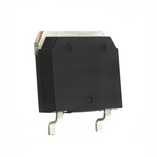
- Package: The product is typically available in a TO-268 package.
- Essence: The essence of the IXGT24N60CD1 lies in its ability to handle high voltages and currents while maintaining efficient power conversion.
- Packaging/Quantity: The product is usually sold individually or in reels of specific quantities.
Specifications
- Voltage Rating: 600V
- Current Rating: 24A
- Package Type: TO-268
- Switching Speed: <100ns
- Operating Temperature Range: -40°C to 150°C
- Isolation Voltage: >2500V
Detailed Pin Configuration
The IXGT24N60CD1 typically has three main pins: collector, gate, and emitter. The pin configuration is as follows: - Collector (C): Pin 1 - Gate (G): Pin 2 - Emitter (E): Pin 3
Functional Features
- High voltage and current handling capability
- Low saturation voltage for reduced power loss
- Fast switching speed for improved efficiency
- Built-in isolation for enhanced safety in high-voltage applications
Advantages and Disadvantages
Advantages
- High voltage and current ratings
- Low saturation voltage
- Fast switching speed
- Enhanced safety features
Disadvantages
- Higher cost compared to standard transistors
- Requires careful handling due to high voltage capabilities
Working Principles
The IXGT24N60CD1 operates based on the principles of insulated gate bipolar transistors. When a positive voltage is applied to the gate terminal, it allows current to flow between the collector and emitter terminals. By controlling the gate voltage, the device can efficiently switch high currents at high voltages.
Detailed Application Field Plans
The IXGT24N60CD1 is commonly used in various power electronics applications, including: - Motor drives - Inverters - Power supplies - Renewable energy systems - Industrial automation
Detailed and Complete Alternative Models
- IXGN24N60CD1: Similar specifications and characteristics
- IXGT30N60BD1: Higher current rating and similar voltage rating
- IXGH20N60B: Lower current rating but similar voltage rating and characteristics
In conclusion, the IXGT24N60CD1 is a high-voltage IGBT designed for efficient power conversion in various applications. Its high voltage and current ratings, along with fast switching speed, make it suitable for demanding power electronics systems.
Word count: 410
10個與IXGT24N60CD1在技術方案中應用相關的常見問題與解答
What is the maximum voltage rating of IXGT24N60CD1?
- The maximum voltage rating of IXGT24N60CD1 is 600V.
What is the maximum continuous current rating of IXGT24N60CD1?
- The maximum continuous current rating of IXGT24N60CD1 is 24A.
What type of package does IXGT24N60CD1 come in?
- IXGT24N60CD1 comes in a TO-268 package.
What are the typical applications for IXGT24N60CD1?
- IXGT24N60CD1 is commonly used in motor drives, inverters, and power supplies.
What is the on-state voltage drop of IXGT24N60CD1 at its rated current?
- The on-state voltage drop of IXGT24N60CD1 at its rated current is typically around 1.8V.
Does IXGT24N60CD1 have built-in protection features?
- Yes, IXGT24N60CD1 has built-in overcurrent and overtemperature protection.
What is the thermal resistance of IXGT24N60CD1?
- The thermal resistance of IXGT24N60CD1 is typically around 1.25°C/W.
Can IXGT24N60CD1 be used in high-frequency switching applications?
- Yes, IXGT24N60CD1 is suitable for high-frequency switching due to its fast switching characteristics.
Is IXGT24N60CD1 RoHS compliant?
- Yes, IXGT24N60CD1 is RoHS compliant, making it suitable for environmentally friendly designs.
What are the recommended storage and operating temperature ranges for IXGT24N60CD1?
- The recommended storage temperature range for IXGT24N60CD1 is -55°C to 150°C, and the recommended operating temperature range is -40°C to 150°C.